Oscilloscope Tracings II
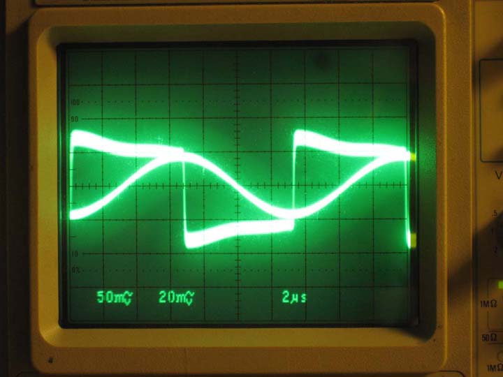
We will monitor this relationship. We are at resonance when our PLL chip keeps Vc ninety degrees leading Vinverter. Now, we can easily exceed the chips maximum input voltage, so we need to clip the top and bottom the the capacitor voltage, and keep it to a maximum of 15v. We do this with some clamping diodes yeilding this waveform, which will be the signalin input on pin 14 of the HEF4046.
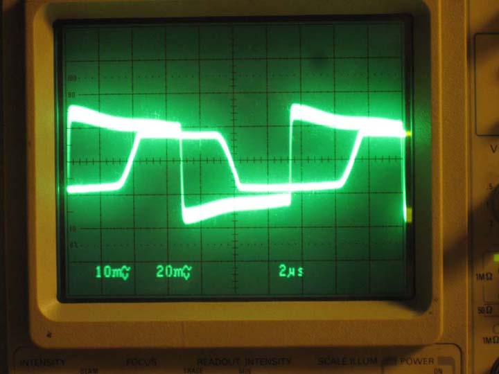
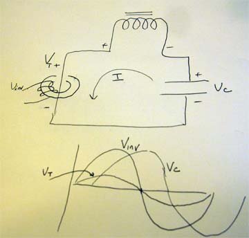
Below is a diagram of the scoped voltages. Using a differential probe, the positive lead goes to the positive inverter lead going to the toroid and the negative to the negative lead. Using a second differential probe we scope the + and - ends of the capacitor tank. Vc will lag Vinv or Vtank. We will have to invert the Vc waveform, that is shift it 180 degrees, in order for the PLL to work, which I will discuss shortly.
Now, we are ready to talk about the phase locked loop chip - the HEF4046. After this discussion, we will have enough information to understand the workings of the inverter and how it maintains a lock on the resonance.