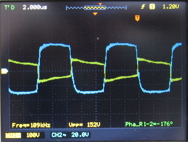
Oscilloscope Tracings III
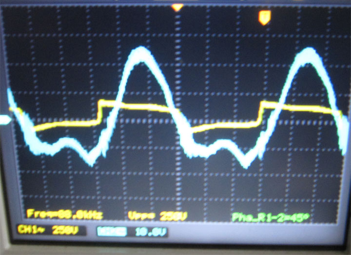
Here is another image. The waveform is different from above, but still bizarre and not a good sinusoid.
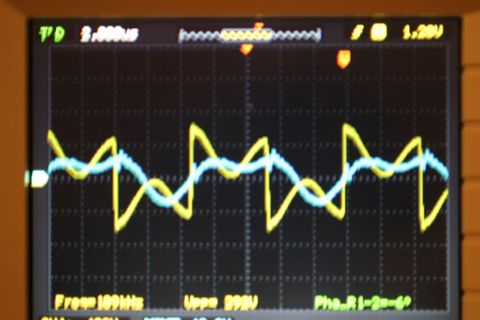
This is the inverter voltage (yellow) and gate drive (blue). Notice how the voltage heavily sags and the gate signal is no longer a clean square wave.
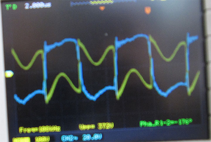
Here is another gate wave that is abnormal taken at a different time.
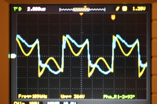
As you can see, I was getting strange waveforms and I did not know why.
At first I thought it was the mosfets so I swapped them out. When that failed to fix the problem I redid the gate resistors and shielding. Then, I pulled out the inverter capacitors and replaced them. Still no good. Frustrated, I took out the board and replaced the gate drive capacitors. When this failed I redid the entire circuit board thinking I was getting some type of cross-talk or a failed component. I saved myself from buying another tank capacitor by connecting the coupling transformer to another LC tank. Again, I had the same problem.
I thought I checked everything and I couldn't understand how the waveform had deteriorated. Sometimes, the current appeared to go at twice the frequency of the inverter voltage. Then, I had a final thought. I started looking at my high voltage DC supply. I must have reconnected the HV wires to the inverter early in the summer. Notice in the picture how they are not together.
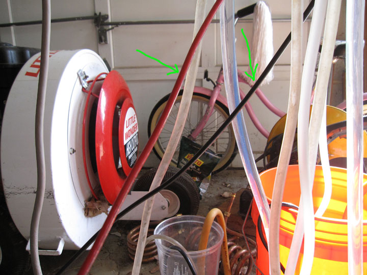
They should be together to cancel out any stray inductance as shown below.
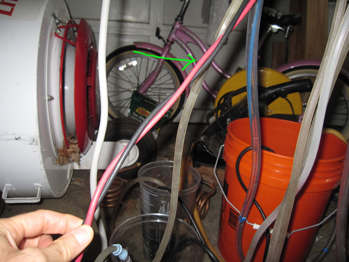
Amazingly, after days of racking my brain, this simple solution was all that was needed. I twisted the HV wires close (as I had done in the past) and made sure they were close on my inverter board before splitting to each of the HV rails. At the frequency I am driving my coil, stray inductance and capacitance on the HV lines is significant and clearly affected my waveforms. Not only did this affect the LC tank, but it affected the gate signal and the voltage supply signal to the circuitry, making things even worse. Hopefully, my experience will make someone's life easier if these symptoms appear.
Below are the waveforms for the inverter voltage and current immediately after this repair. I have the frequency deliberately higher than resonance to prevent reverse currents.
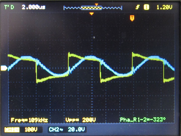
Below is the gate signal after this repair.
