Ferrite Toroids, RCL Theory and Transformer Coupling
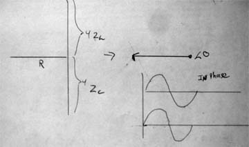
Below we have a RCL circuit with a resistance of 4R, Zl = 4ohms and Cl = 3ohms. The reactive impedance cancels to 1ohm, giving us a phase shift of 18degrees leading. The inductor wins and the inductor voltage leads the current. There is only one current running through the series circuit. You can also say the inductor voltage leads the voltage across the resistor, because the voltage and current of the resistor are in phase. Remember, the voltage drop across an inductor is a reaction against a change in current through it. The instantaneous voltage is zero when the current is at a peak because the change in current is zero, manifested by the zero slope.

If the inductive and capacitive reactance cancel out the phase shift is zero. The current in the circuit is in phase with the voltage.
Now here is an important point. The maximum power transfer will occur when the current is in phase with the voltage.
So, at resonance, the current in the series circuit is in phase with the voltage source. If we are out of resonance the current phase is shifted from zero with respect to the voltage. If there is more inductive reactance the current lags the voltage; if there is more capacitive reactance the current leads the voltage. You can also say the capacitor voltage lags the current.
What is the voltage source for the series tank? It is our coupling transformer. I am experimenting with different materials and turns, but right now I am using an iron powered core from Amidon Corp made from Type 3 material. This material is good from frequencies between 0.05Mhz and 0.5Mhz. I used two toroids. Each is 2.25" in diameter and 0.565" thick. I wound 14g wire around for 20-26 turns. I am still trying to figure out the optimum turns and the best material. The lower the turns the greater greater the exciting voltage to the tank. However, magnetization current goes up as does the load on the inverter.
Below are the two toroids. I use two to prevent saturation. I wonder how three would do?

Here I have wound 14g wire around. The transformer does not impart a phase shift if place on the tank correctly. If you flip it around you will introduce a 180 degree shift which will prevent the PLL from locking onto the frequency. Just turn it around. Which way is the right way? Use the right-hand rule.

Here is a solenoid with the current flowing in the direction shown. Put your right thumb in the direction of the current and your fingers curl in the direction of the B field. The field outside of the coil is not important to us; the field inside the solenoid sums to one large field going from right to left. If we had a metal bar or part of the toroid's arc inside, the field would travel through it.

So here is a mock-up of the coupling transformer. The current travels to the positive terminal of our toroid transformer output. Using the right hand rule we can realize the direction of the B field for each turn. The black arrow on the toroid shows the direction the field travels in the core. Using the right-hand rule again we see that the current travels through the copper tubing from left to right towards the positive terminal of our RLC tank. We will use this as the positive lead for monitoring our tank capacitor voltage later. If you are unsure which end is which you can wind a few turns of wire as a secondary and scope the ends. The voltages in and out should be in phase.
